9.3 ACCOMMODATION OF THERMAL EXPANSION
Stainless steel metal hoses are slightly elastic in the longitudinal direction. It is possible to reduce the length by max. 0.6% without compromising the pressure resistance of the hose. Further compression is therefore not allowed.
The following designs are possible to compensate thermal expansion.
9.3.1 Installation plan
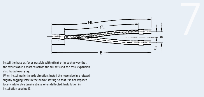
Straight or with displacement
Movement: lateral (not for vibrations!)
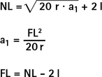
| installation distance E ≈ NL · 0,994 minimum hose length FL min = 8 · a1 |
||
| E | mm | installation distance in axis direction |
| NL | mm | total length of the metal hose |
| FL | mm | free-moving hose length |
| r | mm | smallest bending radius for frequent movements |
| l | mm | length of a connection part |
| a | mm | total lateral path = 2 · a1 |
| a1 | mm | lateral path from the middle axis (max.100 mm) |
Example 7
Example
Rattay stainless steel corrugated hose DN 20 Type HR I/S, on both sides screw connections made of stainless steel, Fig. 101.
Movement data
- Movement accommodation a = 60 mm
Calculation
a1 = ![]() = 30 mm
= 30 mm
r = 170 mm see hose table
l = 79 mm see dimension table connection parts
NL = ![]() + 2 · 79 = 477 mm
+ 2 · 79 = 477 mm
FL = 477 - 2 · 79 = 319 mm
E = 477 · 0.994 = 474 mm
i.e. for installation in axis position (middle position) must be shortened by 3 mm
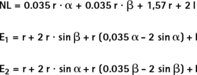
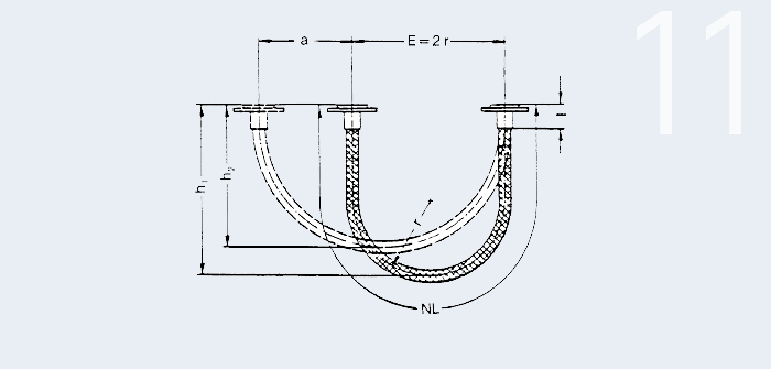
9.3.2 Installation plan

90° elbow
Movement from one direction (not for vibrations!)
![]() Value from bending angle table
Value from bending angle table
The bending angle may not exceed max. 60°.
| E1 | mm | installation distance |
| E2 | mm | installation distance |
| NL | mm | total length of the metal hose |
| r | mm | smallest bending radius |
| l | mm | length of a connection part |
| a | mm | expansion accommodation |
| bending angle |
Example 8
Example
Rattay stainless steel corrugated hose DN 25 Type HR I/S, on both sides screw connections made of stainless steel, Fig. 114.
Movement data
- Movement accommodation a = 60 mm
Calculation
r = 205 mm see hose table
l = 85 mm
![]() =
= ![]() = 0,293
= 0,293 ![]() 27° see bending angle table
27° see bending angle table
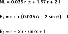
NL = 0.035 · 205 · 27 + 1,57 · 205 + 2 · 85 = 685.7 mm (Order length NL = 700 mm)
E1 = 205 + 205 (0.035 · 27 - 2 · sin 27°) + 85 = 297.6 mm
E2 = 205 + 2 · 205 · sin 27° + 85 = 476.1 mm
9.3.3 Installation plan

90° elbow
Movement from two directions (not for vibrations!)
| E1 | mm | installation distance |
| E2 | mm | installation distance |
| NL | mm | total length of the metal hose |
| r | mm | smallest bending radius |
| l | mm | length of a connection part |
| a1 | mm | expansion accommodation axial |
| a2 | mm | expansion accommodation lateral |
| bending angle = + |
||
| β | bending angle = + |
Example 9
Example
Rattay stainless steel corrugated hose DN 32 Type HR I/S, on both sides screw connections made of stainless steel, Fig. 101.
Movement data:
- axial a1 = 66 mm
- lateral a2 = 25 mm
Calculation
r = 260 mm see hose table
l = 96 mm see dimension table connection parts
![]() =
= ![]() = 0.253
= 0.253 ![]() 28° see bending angle table
28° see bending angle table
β = ![]() = 0.0916
= 0.0916 ![]() 18° see bending angle table
18° see bending angle table
NL = 0.035 · 260 · 28 + 0.035 · 260 · 18 + 1.57 · 260 + 2 · 96 = 1,018.8 mm
E1 = 260 + 2 · 260 · sin 18° + 260 (0.035 · 28 - 2 · sin 28°) + 96 = 527.4 mm
E2 = 260 + 2 · 260 · sin 28° + 260 (0.035 · 18 - 2 · sin 18°) + 96 = 603.2 mm
9.3.4 Installation plan
90° elbow
Movement from two directions (not for vibrations!)
| E1 | mm | installation distance |
| E2 | mm | installation distance |
| NL | mm | total length of the metal hose |
| r | mm | smallest bending radius |
| l | mm | ength of a connection part |
| a1 | mm | expansion accommodation horizontal |
| a2 | mm | expansion accommodation vertical |
| bending angle = + |
||
| β | bending angle = + |
Example 10
Example
Rattay stainless steel corrugated hose DN 40 Type HR I/S, on both sides screw connections made of stainless steel, Fig. 114
Movement data
- Expansion accommodation a1 = 78 mm horizontal
- Expansion accommodation a2 = 23 mm vertical
Calculation
r = 310 mm see hose table
l = 95 mm
![]() =
= ![]() = 0.252
= 0.252 ![]() 28° see bending angle table
28° see bending angle table
β = ![]() = 0.0742
= 0.0742 ![]() 16° see bending angle table
16° see bending angle table
NL = 0.035 · 310 · 28 + 0.035 · 310 · 16 + 1.57 · 310 + 2 · 95 = 1,154.1 mm
E1 = 310 + 2 · 310 · sin 16° + 310 (0.035 · 28 - 2 · sin 28°) + 95 = 588.6 mm
E2 = 310 + 2 · 310 · sin 28° + 310 (0.035 · 16 - 2 · sin 16°) + 95 = 698.9 mm
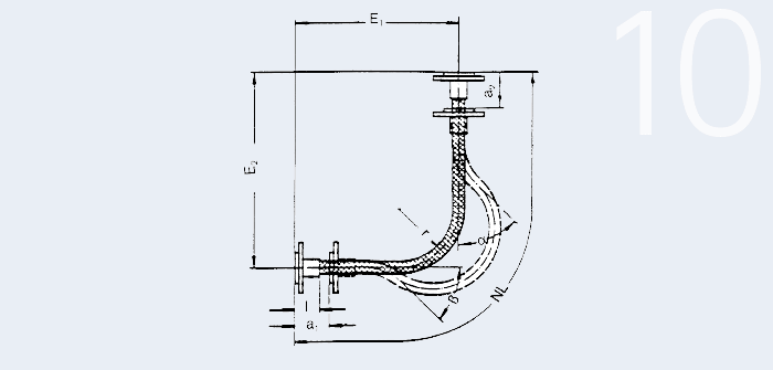
9.3.5 Installation plan
180° elbow
Movement from one direction
| E | mm | installation distance |
| NL | mm | total length of the metal hose |
| r | mm | smallest bending radius |
| l | mm | length of a connection part |
| a | mm | lift |
| h1 | mm | max. height of the 180° elbow |
| h2 | mm | min. height of the 180° elbow |
Example 11
Example
Rattay stainless steel corrugated hose DN 40 Type HR I/S, on both sides screw connections made of stainless steel, Fig. 114.
Movement data
- Lift a = 150 mm
Calculation
r = 205 mm mm see hose table
l = 85 mm
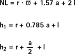
NL = 205 · ![]() + 1.57 · 150 + 2 · 85 = 1,049.2 mm (Order length NL = 1,100 mm)
+ 1.57 · 150 + 2 · 85 = 1,049.2 mm (Order length NL = 1,100 mm)
h1 = 205 + 0.785 · 150 + 85 = 407.8 mm
h2 = 205 + ![]() + 85 = 365 mm
+ 85 = 365 mm
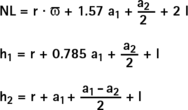
9.3.6 Installation plan
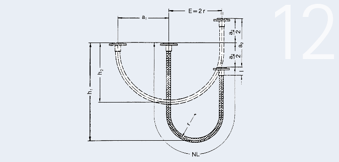
180° elbow
Movement from one direction
| E | mm | installation distance |
| NL | mm | total length of the metal hose |
| r | mm | smallest bending radius |
| l | mm | length of a connection part |
| a1 | mm | total travel horizontal |
| a2 | mm | total travel vertical |
| h1 | mm | max. height of the 180° elbow |
| h2 | mm | min. height of the 180° elbow |
Example 12
Example
Rattay stainless steel corrugated hose DN 40 Type HR I/S, on both sides screw connections made of stainless steel, Fig. 114.
Movement data
- Hub a1 = 210 mm horizontal
- Hub a2 = 175 mm vertical
Calculation
l = 89 mm
r = 310 mm see hose table
NL = 310 · ![]() + 1.57 · 210 +
+ 1.57 · 210 + ![]() 2 · 89 = 1,568.6 mm (Order length NL = 1,600 mm)
2 · 89 = 1,568.6 mm (Order length NL = 1,600 mm)
h1 = 310 + 0.785 · 210 + ![]() + 89 = 651.4 mm
+ 89 = 651.4 mm
h2 = 310 + ![]() + 89 = 416.5 mm
+ 89 = 416.5 mm